-
Shop Parts
- Shop Accessories
- Shop Overland
-
Shop by Vehicle
![Select Vehicle]() Select Your Vehicle
Select Your Vehicle - Videos & Resources
Sign in to my account
Instructions
Heater Blower Motor Kit for Range Rover Classic
Applies To:
Item: 8844
Fits: Range Rover Classic | '90 - '94
Heater Box Rebuild... Continued
12. You can now slide the heater core out of the housing. (See photo 70)
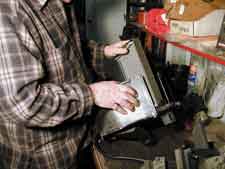
Photo 70
13. Make sure that you clean the core with compressed air before reassembly. (See photo 71)
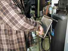
Photo 71
14. Using large diagonal cutters clip the 3 mounting posts holding the blower motor in place. (See Photo 72) Remove motor and blower wheel assembly from heater housing.
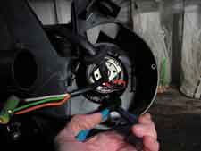
Photo 72
15. CRITICAL STEP: Using small diagonal cutters remove as much of what remains of the motor mounting posts as possible. Clean out whatever remains of the 3 mounting posts with a Dremel tool or a grinder. You want the surface that the new motor clamp mounts against to be as flat as possible. Any unevenness will skew the mounting of the motor and may cause rubbing once the 2 halves of the heater housing are reassembled. The goal is to keep the mounting surface perpendicular with the axis of rotation of the motor and wheel. (Grinding shown in photo 73)
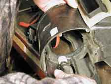
Photo 73
16. CRITICAL STEP: The diameter of the new motor is slightly larger than the original motor (2.75 vs. 2.50 inches). Because of this there is a chance that the operation of the Fresh Air Flap will be vulnerable to interference with the new motor mounting bracket. For this reason it is advised that a rasp or file is used to shorten the part of the flap that passes by the motor mount. (The flap with the bracket installed is shown in photo 74)
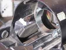
Photo 74
17. Looking at the enclosure half from the opposite side where we were just grinding the mounting posts away, locate the Mounting Ring over the molded lip with the studs facing up. The ring should rest flat against the enclosure and self-center around the lip. Align the mark on the ring with the edge of the opening as shown in photo 75. This should align the small locating holes directly over the places where you ground the old mounting posts out. Feel underneath to ensure that the pilot holes we will be drilling in the next step will be located over the area where the old plastic posts were located.
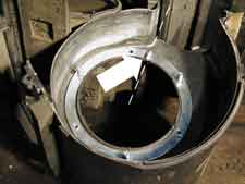
Photo 75
18. Being very careful not to move the ring, use a 1/8 inch drill to drill pilot holes through the 3 holes in the ring and through the plastic of the enclosure. (See photo 76)
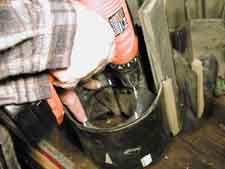
Photo 76
19. Enlarge the holes drilled in the last step with a 3/16 inch drill bit. Flip the Mounting Ring over and press the studs through the holes you just enlarged. It will be a tight fit so that the ring stays in place as we turn the enclosure over and install the Motor Mounting Clamp. (See photo 77)
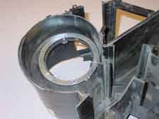
Photo 77
20. Turn the enclosure over and install the Motor Mounting Clamp as shown in photo 78, allowing access to the tightening nut. Install the external tooth lock washers over the studs and loosely tighten the nylon insert locknuts on the studs (We will tighten these in a later step.)
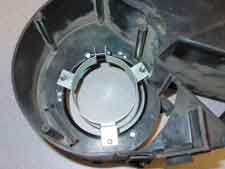
Photo 78
21. Clip the Black and Red wires from the old motor (See photo 79). Feed these wires through the enclosure between the space between the Motor Mounting Clamp and the blower wheel opening. (See photo 80)
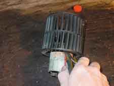
Photo 79
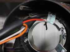
Photo 80
22. Pulling the wires though the enclosure so that you have adequate slack solder these wires to the wires on the motor matching the colors. Make sure to slip the heat-shrinkable tubing over the wires before you solder them. (See photo 81). It is important that the wires are soldered and not crimped together. The vibration that this unit is likely to see will cause a crimped connection to eventually fail. You would not want to repeat this entire procedure just to fix a bad connection.
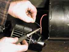
Photo 81
23. After the wires are soldered (and cooled) move the shrinkable tubing over the connection and shrink with a heat gun. (See photo 82)
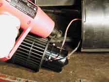
Photo 82
24. Slide the motor through the enclosure and into the clamp. (See photo 83) Slide it into the clamp such that about 1/2 inch of the motor body is past the edge of the clamp. You can verify that it is positioned properly by looking at the blower wheel. The center point of the wheel should be approximately in line with the edge of the housing. (See photo 84)
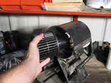
Photo 83
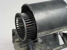
Photo 84
25. Using a thin walled 3/8 socket and 5/32 Allen Wrench tighten the motor clamp nut and the 3 nuts securing the clamp to the enclosure. (See photos 85 and 86)
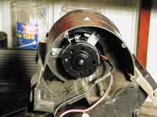
Photo 85
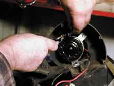
Photo 86


What Our Customers Are Saying


