-
Shop Parts
- Shop Accessories
- Shop Overland
-
Shop by Vehicle
![Select Vehicle]() Select Your Vehicle
Select Your Vehicle - Videos & Resources
Sign in to my account
Instructions
Heater Blower Motor Kit for Range Rover Classic
Applies To:
Item: 8844
Fits: Range Rover Classic | '90 - '94
Heater Box Rebuild... Continued
26. Reinstall the heater core and the heater core panel.
27. Lining all of the flaps back up, slide the halves back together making sure that the fresh air flap is lined up with the "V" in the housing like you did during disassembly. This step requires a little patience. Using a pick can help in guiding the shafts into their locations in the enclosure. (See photos 87, 88, and 89) It may be necessary to remove the defrost ducts to get at the shaft openings. (See photos 90 and 91)
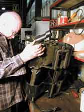
Photo 87
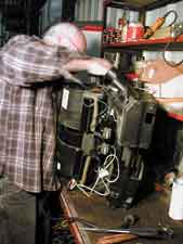
Photo 88
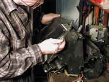
Photo 89
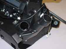
Photo 90
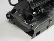
Photo 91
28. After the halves are back together, use a few clips (or the screws) to hold everything together. Make sure that all the flaps move freely and that the blower motor turns freely without any rubbing or obstruction. NOTE: If you have a couple of test clips, you might want to connect the Black and Red wires in the blower connector to the battery and test that the blower works correctly. {Once again, you don't want to finish this project only to discover there is something wrong with the operation of the blower motor.}
29. Put all the clips and clamp rings back on the unit securing the halves. Put the 2 screws back in as shown in photo 92.
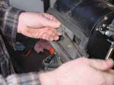
Photo 92
30. Put new pop rivets in place of the ones that were previously drilled out.
31. Put the resistor back on the heat shield and line the shield up with the slot in the enclosure. (See photo 93 and 94) Making sure that any excess wire will not interfere with any moving part reinstall the left side plate with the 6 screws. (See photo 95)
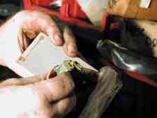
Photo 93
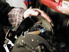
Photo 94
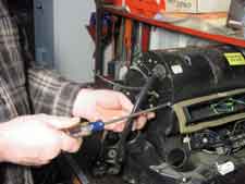
Photo 95
32. Reinstall the right side plate (6 screws, photo 96)
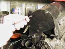
Photo 96
33. Reinstall the Recirculation Air Flap Actuator with the 2 screws and reattach the control arm. (See photos 97 and 98)
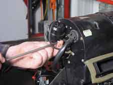
Photo 97
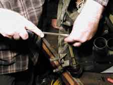
Photo 98
34. Clip the adjusting rod back into the clip that was removed in step D above.
35. Reinstall the foot-well ducts that were removed in step 34 above.
36. Reinstall the defrost ducts if they were removed in step 35 above.
37. Put duct tape along the seams on the bottom of the unit where the foot-well ducts meet the enclosure body.
38. Reinstall the foam around the heater pipes. (See photo 99)
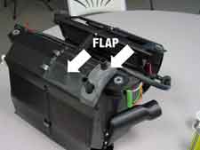
Photo 99
39. Make sure that the electrical control cable is in the position as shown in photo 100. This will help to ensure that it is not in the way when it is repositioned into the vehicle.
Photo 100


What Our Customers Are Saying


