-
Shop Parts
- Shop Accessories
- Shop Overland
-
Shop by Vehicle
![Select Vehicle]() Select Your Vehicle
Select Your Vehicle - Videos & Resources
Sign in to my account
Test Procedure and Instructions for Shuttle Valve Switches
Applies To:
Discovery Series II | '99-'04
ABS Module Valve Kit - Part # SWO500030
DIAGNOSTIC AND REPAIR PROCEDURE
INVESTIGATE FAULT CODES AND REPAIR WIRING AS INDICATED
NOTE: Wiring faults may be intermittent due to hidden breaks and poor connections. Also, before completing this check, start by looking for common faults with your shuttle valve or ABS sensor. See this Tech Tip for more information.
- When checking for wiring faults, always try to provoke intermittent faults by flexing wires while checking.
- For connector views not detailed in this bulletin, refer to the appropriate Electrical Library.
- For all electrical repairs refer to the guidelines shown in the Discovery 1999MY Electrical Library LRL0529 (Introduction, Harness Repairs).
NOTE: If a fault is confirmed and a rectification carried out, the step/rectification must be retested and then the remainder of the diagnostic procedure should be completed.
1. Position the ignition to the OFF position and perform the following:
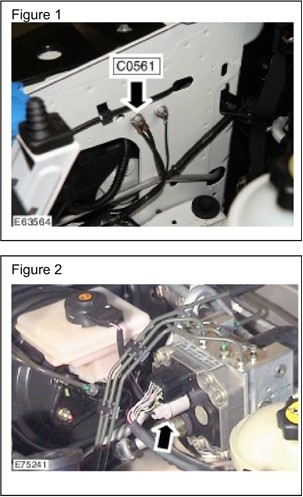
- Inspect the ground stud connection C0561-1 for damage and corrosion. (Figure 1 below)
- If the ground stud is damaged or corroded clean the eyelet and stud and tighten the nut to 10 Nm (7.5 lbf-ft).
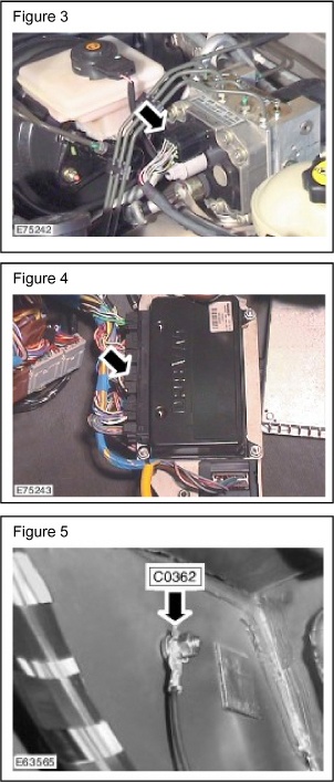
- Check for continuity between the ground stud C0561-1 and the black wire on the ABS modulator body connector C0500. (Figure 2 below)
- If there is no continuity, or intermittent continuity when the wire is flexed, repair the damaged wire and ensure the splice is correctly crimped and sealed.
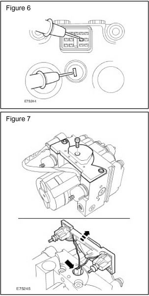
2. Disconnect and check the 13-pin connector at the ABS modulator (C0501). (Figure 3 below)
3. Disconnect the 15-pin connector C0506 at the Self Leveling and Anti-lock Braking (SLABS) ECU. (Figure 4 below)
4. Inspect both connectors for moisture ingress or corrosion and correct as follows:
- If moisture or corrosion is present, dry and clean the connectors.
- Repair corroded connectors as necessary.
5. With connectors C0501 and C0506 disconnected perform the following:
- Check for continuity between pin 6 of the 15-pin SLABS ECU connector (C0506) and pin 9 of the 13- pin ABS modulator connector (C0501) yellow/green wire.
- If there is no continuity (or intermittent continuity when the wire is flexed), repair as necessary and ensure the wire is correctly crimped and soldered.
- Check for continuity between pin 3 of the 15-pin SLABS ECU connector (C0506) and pin 8 of the 13- pin ABS modulator connector (C0501) black/slate wire.
- If there is no continuity (or intermittent continuity when the wire is flexed), repair as necessary and ensure the wire is correctly crimped and soldered.
6. Disconnect the 18-pin SLABS ECU connector (C0504).
7. Check for continuity between pin-12 of C0504 and the ground connection located under the left-hand side of the fascia (C0362 - black wire). (Figure 5 below)
8. If there is no continuity (or intermittent continuity when the wire is flexed), repair as necessary and ensure the wire is correctly crimped and soldered.
9. Connect the connectors to the SLABS ECU and ABS Modulator.
10. If repairs were completed, clear all logged codes using T4 and perform the following:
- Road test the vehicle.
- If no DTCs return, no further action is required.
DIAGNOSE ABS MODULATOR AND REPAIR AS INDICATED
CAUTION: The safety precautions detailed in the Workshop Manual relating to braking systems must be adhered to.
NOTE: Discovery Series II 1999MY onwards Workshop Manual Section 70, Brakes - Modulator unit - ABS (70.65.49)
1. If no wiring concerns were found during the continuity checks, refer to GTR section 70.65.49 and remove the ABS modulator from the vehicle.
2. Place the ABS modulator on clean work surface and check for continuity between pin 8 of the 13-pin modulator connector (C0501-8) and the single adjacent modulator ground pin (C0500-1). (Figure 6 below).
3. If there is no continuity in the test above, obtain a new ABS modulator and go to the INSTALLATION AND FINAL VERIFICATION section.
CAUTION: This procedure should be carried out in a clean working environment.
NOTE: There may be a slight covering of brake fluid behind the black plastic cover when removed. This is normal and is not a cause for concern. The shuttle valve switches are located behind the black plastic cover opposite the hydraulic ports.
4. If there is continuity in the test above in step 2, remove the plastic cover from the modulator as follows: (Figure 7 below)
- Remove the three cap-head bolts holding the cover in place.
- Carefully pull the cover away from the modulator in order to get access to the SVS connector behind the cover.
- If there is evidence of excessive brake fluid leakage (fluid dripping from the cover when the cover is removed), obtain a new ABS modulator and go to the INSTALLATION AND FINAL VERIFICATION section.
- If there is no brake fluid present, pull the connector apart and remove the shuttle valve switches and black plastic cover as an assembly.
- Clean any excess residual thread lock from the SVS mounting bolt holes.
CAUTION: The black plastic cover must be secure and may not be cracked when installed.
5. Install the new shuttle valve switch pack from the service kit as follows:
- Connect the electrical connector.
- Carefully push the cover into the modulator.
- Install the three cap-head screws from the service kit and tighten to 4Nm (3lbf-ft).
6. Measure the resistance between pin 9 on the 13-pin modulator connector (C0501-9) and the single adjacent modulator ground pin (C0500-1).
7. If the resistance value observed is outside the 3020 Ohms ±30 Ohms limit, obtain a new ABS modulator and go to the INSTALLATION AND FINAL VERIFICATION section.
INSTALLATION AND FINAL VERIFICATION
1. Refer to GTR Section 70.65.49 and install the ABS modulator from the vehicle or the new unit if testing indicated replacement was required.
2. Clear any logged DTCs using T4 and disconnect the diagnostic equipment from the vehicle.
3. Road test the vehicle including a number of drive cycles to verify that none of the SVS DTCs return and include the following elements in the road test:
- Light acceleration.
- Light braking.
- Ignition resets while stationary.
4. Connect T4 and verify that no SVS DTCs have returned.
5. Verify that the Internal ECU Data Shuttle Valve Switch Failure Count (0DH LSB) is zero.
6. If the failure count is not zero or if any SVS DTCs have returned, replace the ABS modulator with a new unit.
What Our Customers Are Saying


