-
Shop Parts
- Shop Accessories
- Shop Overland
-
Shop by Vehicle
![Select Vehicle]() Select Your Vehicle
Select Your Vehicle - Videos & Resources
Sign in to my account
Air Suspension Configuration Device
Applies To:
Item: 7982
For LR3 / LR4 (L319) & Range Rover Sport (L320)

Function and Installation:
Requirement: When replacing a dynamic air spring suspension with a coil spring suspension, the EAS (Electronic Air Suspension) ECU (Electronic Control Unit) will generate error messages due to the lack of control of the coil spring suspension.
IMPORTANT! The device will automatically store the Vehicle Identification Number (VIN) of the first vehicle that it is connected to. It will then be permanently locked to that vehicle.
NOTE: The EAS ECU is located on the left side (driver) of the vehicle for the LR3 and LR4 (L319) and Range Rover Sport (L320).
Before You Start:
- Ensure that the battery is fully charged.
- Ensure the vehicle is in Park / Neutral with the Parking Brake applied.
- It is recommended that the headlights are turned off throughout the configuration process.
- Do not start the engine at any point during the configuration process.
Installing the Override Module:
Tools Needed:
- Flat Blade Screwdriver (or Panel Popper to remove Foot Rest Top)
- 10mm Socket with extension
- #15 Torx Driver
- Phillips Screwdriver
- Wire Citters
- Wire Strippers
Procedure:
Access to EAS ECU:
1. Remove the Foot Rest by first popping the cover off, then remove 2 ea. nuts. (See figure 1 & 2)
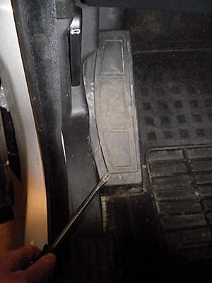
Figure #1.
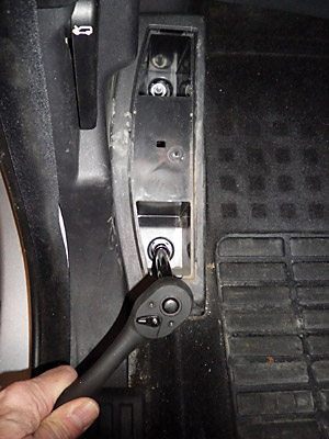
Figure #2.
2. With the Foot Rest out, you can remove the Left Side Panel by taking out the hood release lever (Torx Screw) and pulling the panel toward you. (See figure 3 & 4)
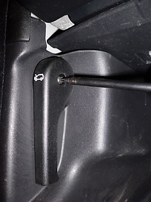
Figure #3.
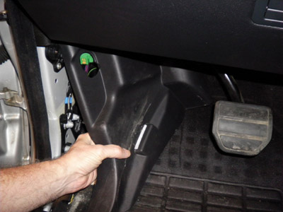
Figure #4.
3. Loosen the 2 screws securing the upper panel and drop it down. You don't need to remove it as long as you can secure it so that it is out of the way as you work on the EAS ECU wiring harness. (See figure 5)
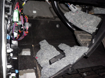
Figure #5.
4. Remove the panel just below the steering wheel by pulling it toward you. It will come right out as seen in this picture. (See figure 6)
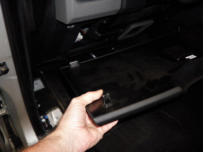
Figure #6.
5. Locate the EAS ECU. It will be mounted fairly high up on the left wall in the cavity that you have just exposed with the removal of the panels. (See figure 7)
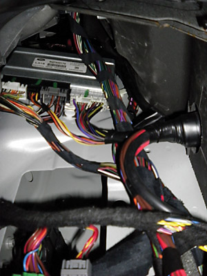
Figure #7.
6. Locate the mounting bolt at the top of the EAS ECU. It will be difficult to see, but you can feel it at the top of the ECU. Use the 10mm socket to remove the bolt. The ECU can then be pulled down by first pushing it up a bit to free it from the mounting "pegs" along the bottom of the unit. With the unit free of its mounting you can maneuver it down allowing access to the connectors and wiring harness. (See figure 8)
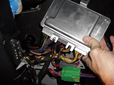
Figure #8.
7. Locate connector C0867 and unplug it from the ECU. (See figure 9)
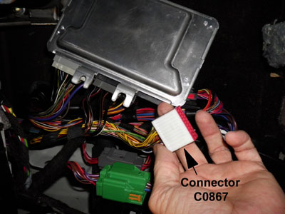
Figure #9.
8. Examine the backside of the connector and identify the 2 Data wires. On the LR3 or Range Rover Sport, the wires are in position 16 and 19 of the connector. (See figure 10) They will be twisted together. (See figure 12)
For the LR4, the wires are in position 17 and 18 of the connector. (See figure 11) Note: On LR4 wires and pin configurations may be slightly different than for the LR3 / Range Rover Sport, but the pin numbers and colors are accurate.
Use For LR3 or Range Rover Sport:
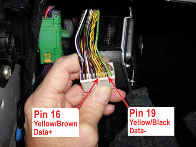
Figure #10.
Use For LR4:
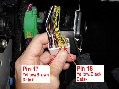
Figure #11.
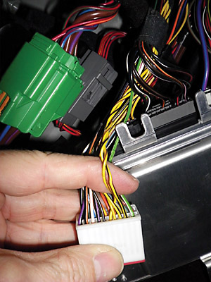
Figure #12.
9. Cut the 2 data wires. Be sure to double (and triple) check the wires before cutting. As you might imagine, cutting the wrong wires will cause you much difficulty as you proceed with this installation. (See figure 13)
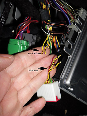
Figure #13.
10. Strip the insulation from each end of the 2 Data wires you just cut (4 strips total) and strip all 6 wires on the Filter Module Wiring Harness (supplied with the 7982 module) by 5/16 inch. (See figure 14)
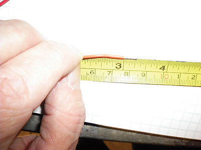
Figure #14.
11. Using the Posi-Lock wire splices connect the Data Wires to the Filter Module Wiring Harness as follows:
NOTE: It is VERY important that you take care to get the proper wires spliced together.
Vehicle Wires |
Filter Module Wiring Harness |
Data +, Yellow/Brown, ECU Side |
Brown |
Data +, Yellow/Brown, Vehicle Side |
Yellow |
Data -, Yellow/Black, ECU Side |
Orange |
Data -, Yellow/Black, Vehicle Side |
Green |
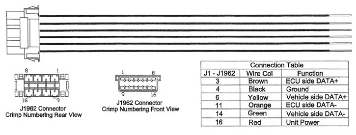
Addendum A.
12. After the Data Wires are spliced, your harness should look like this. (See figure 15)
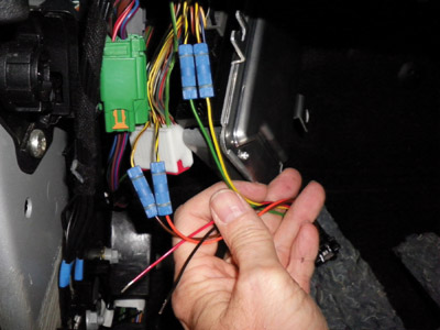
Figure #15.
13. Locate the positive power wire on C0867. It will be in position 20 (next to the Yellow/Black wire you just spliced) (See figure 16)
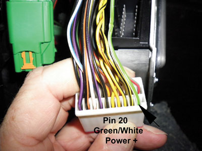
Figure #16.
14. Using the smaller (Red / Brown) Posi-Tap connect the Red wire from the Filter Wiring Harness to the Green/White wire. You do NOT need to cut the wire, we are just tapping into the power on this wire. (See figures 17, 18)
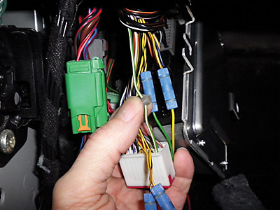
Figure #17.
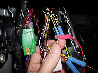
Figure #18.
15. Locate connector C2321, and unplug it from the ECU. (See figure 19)
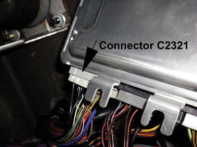
Figure #19.
16. Locate the Black wire in position 24 of C2321 and using the larger Black Posi-Tap connect the Black wire from the Filter Wiring Harness to this wire. Just like with the power wire in step # 14, we are NOT cutting this wire, just splicing. (See figures 20, 21, 22)
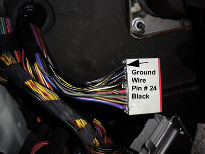
Figure #20.
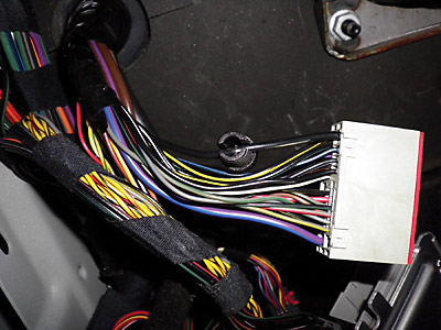
Figure #21.
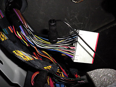
Figure #22.
17. Reinstall all of the panels, and the Foot Rest.
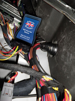
Figure #23.
What Our Customers Are Saying


