-
Shop Parts
- Shop Accessories
- Shop Overland
-
Shop by Vehicle
![Select Vehicle]() Select Your Vehicle
Select Your Vehicle - Videos & Resources
Sign in to my account
Instructions
Land Rover Discovery I Deluxe and Winch Brush Bars
Applies To:
Item: 9402ARBD8/9402ARBD9
Fits: Discovery I | '94 - '99
- c.) Fit the To place the winch motor in the correct location, the winch motor must be rotated 90 degrees, in an anti-clockwise direction when viewed from the motor end. Place the winch on its end and remove the 2 motor retaining bolts. Gently raise the motor just enough to rotate it. Do not completely remove the motor and avoid damaging the gasket. Refit all bolts and tighten. Refer to Diagram 3
- d.) Fit the roller fairlead into the front of the brush bar using the M12 x 30mm bolts, flat washers, spring washers and nuts supplied.
WINCH BARS: FITTING THE 10,000lb WINCH
- a.) Remove the cover of the control box, disconnect the two heavy short black cables and the heavy short red cable and replace with the corresponding cables supplied. Insert the two 1/4" x 1" bolts into the base of the control box and fix in place with 1/4" nuts, flat washers and spring washers. Replace the cover, then fit the control box to the control box bracket using the two 1/4" nuts, washers and spring washers. Then bolt the control box bracket to the bull bar using the M8 x 20mm bolts, flat washers and flange nuts supplied. Refer to Diagram 1.
- b.) To place the winch clutch handle in a convenient location, the winch gearbox must be rotated 2 hole spacings, 72 degrees, in a anti-clockwise direction when viewed from the gearbox end. Place the winch on its end and remove all gearbox bolts. Gently raise the gearbox just enough to rotate it. Do not completely remove the gearbox and avoid damaging the gasket. Refit all bolts and tighten. Refer to diagram 4.
- c.) Fit the roller fairlead into the front of the brush bar using the M12 x 30mm bolts, flat washers, spring washers and nuts supplied.
5.) Attach the number plate to the front of the brush bar using the two M6 x 16mm bolts, flat washers and flange nuts supplied.
6.) Fit the rubber buffers supplied to the brush bar using the M8 flange nuts supplied in the fitting kit.
7.) Drill out the four forward most holes in the chassis rails with a 1/2" drill.
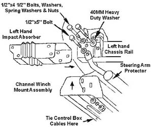
8.) Slide the two impact absorbers over the chassis rails making sure the LH impact absorber is fitted to the LH side and the RH impact absorber is fitted to the RH side. Lift the winch mount cradle (for winch bars only) into position and loosely bolt in place using the 1/2" x 4-1/2" bolts, flat washers, spring washers and nuts in the top and rear chassis holes (the 40mm heavy duty washer must be located on the outside of the rear most hole) and the 1/2" x 5" bolt, flat washers, spring washer and nut in the lower forward chassis hole, passing through the steering arm protector. Refer to diagram 5. (The steering arm protector is not fitted to USA models). NOTE: Due to chassis rail width variations packers with fitting tabs may need to be inserted between the impact absorbers and chassis rails.
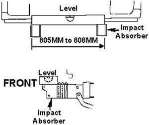
9.) Using a level and a tape measure, adjust both impact absorbers so that they are parallel to each other, horizontal, and have an overall width of between 805mm and 808mm, then tighten the bolts. Refer to diagram 6.
- a.) Lift the winch into place and using the washers supplied in the fitting kit (3/8" for 8 or 9,000lb and 7/16" for 10,000lb) and the bolts and spring washers supplied with the winch, bolt securely into position. NOTE: The gearbox is on the Left hand side for the 8 & 9,000lb winches and on the right hand side for the 10,000lb winch. The winch cable spools from the bottom for all three winches.
- b.) Wire the winch in accordance with the Warn fitting instructions, taking care not to route the cables over sharp edges. Tie the cables from the control box to the channel winch mount assembly using the cable tie supplied.


What Our Customers Are Saying


